Introduction
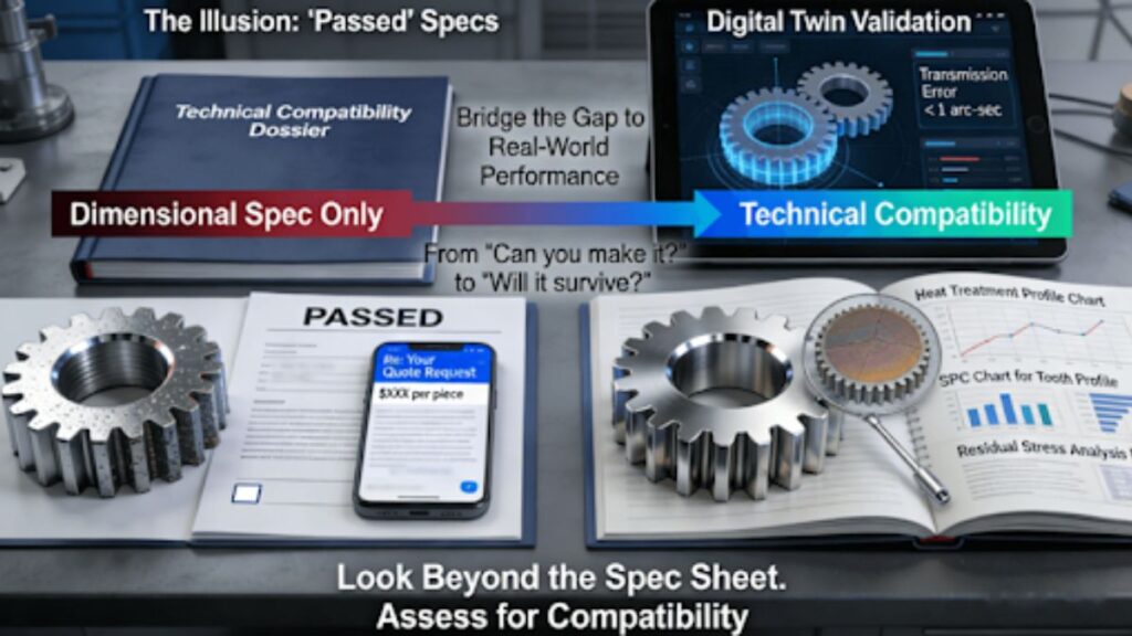
Engineers and procurement teams selecting gear machining services for critical applications — like robotic joints, heavy-duty gearboxes, or high-speed pumps — often face a frustrating dilemma: suppliers meet basic dimensional specifications on the drawing, yet delivered gears perform radically differently in noise, lifespan, or efficiency. This leads to prototype rework, failed tests, and project delays averaging over 30%. The root cause is a traditional supplier evaluation focused on “parameter matching” (e.g., “Can you machine to DIN 6?”) that overlooks the deeper technical compatibility — whether the supplier’s process DNA (methods for controlling heat-treatment distortion, micro-surface finishing) is physically aligned with the gear’s end-use scenario (high shock loads, continuous high-speed operation, corrosive environments).
This article introduces an application-to-capability mapping framework for evaluation. It guides you in looking beyond surface specs to systematically assess a supplier’s deep capabilities in materials science, micro-geometry control, and dynamic performance validation, identifying a partner who ensures your gears’ real-world reliability, not just compliance on paper.
Why Do Gears That Pass Inspection Still Fail in the Field? The Gap Between Dimensional Spec and Functional Performance
This section analyzes common failure modes where gears pass dimensional checks but fail in operation, highlighting the critical distinction between conformance to a drawing and fulfillment of a functional requirement.
1. The Illusion of the “Good” Part: A Case Study in Micro-Pitting
Consider a helical gear that passes all dimensional and runout checks. In the field, under high-frequency cyclic loading, it develops premature micro-pitting on the tooth flanks, leading to unacceptable noise. The root cause isn’t a measured dimension but the residual stress distribution introduced during grinding. A process that left subsurface tensile stress created a perfect initiation point for fatigue cracks, invisible during a standard first-article inspection. The gear was dimensionally “good” but functionally flawed.
2. Dimensional Spec vs. Design Intent: The Core Disconnect
A gear drawing with tight tolerances (e.g., per ASME Y14.5) defines the allowable geometric boundaries. However, it does not specify the process to achieve them or guarantee the resulting material integrity and surface characteristics that dictate performance. Two suppliers, both achieving DIN 6 accuracy, can produce gears with vastly different surface roughness, hardness gradients, and residual stress states, leading to completely different behaviors under load. The true measure of quality is the realization of design intent, not merely dimensional compliance.
3. Assessing from the Application Backward
To bridge this gap, evaluation must start with the end-use. Ask: “What are the failure modes in this application?” and work backward to define the necessary material and process controls. This shifts the focus from “Can you make this shape?” to “Can you make this shape survive and perform in this specific environment?” To comprehensively understand the methodology for bridging drawing specifications to functional performance, this guide on selecting gear machining services provides a complete framework from application analysis to supplier vetting.
What is “Technical Compatibility” in Gear Manufacturing? Mapping Process DNA to Application Scenarios
This section defines the four dimensions of “technical compatibility,” explaining how a supplier’s specific process choices and controls must align with the physical demands of the gear’s application to ensure success.
1. Material and Heat Treatment Compatibility
Compatibility starts at the atomic level. For a high-load gear in 20CrMnTi alloy steel, the supplier’s mastery of the complete carburizing-quenching-tempering cycle is critical. The compatibility question is: Does their controlled atmosphere furnace and quenching process produce the optimal case hardness depth and core toughness gradient for your load spectrum? An incompatible process may yield the correct surface hardness but with excessive retained austenite or undesirable grain growth, compromising fatigue life.
2. Micro-Geometric and Surface Integrity Compatibility
Beyond macro-dimensions lies the micro-world. The surface texture (lay, Ra, Rz) produced by a supplier’s final grinding or honing process directly impacts lubrication. For a high-speed gear, a specific cross-hatch pattern may be needed to retain oil and form a stable hydrodynamic film. An incompatible, randomly oriented finish can lead to scuffing and elevated operating temperatures. This level of control is a hallmark of deep process knowledge.
3. Dynamic Performance and Proactive Compensation Compatibility
Will the gear perform under load? A compatible supplier uses profile and lead modifications not as a standard offering, but as a calculated compensation for predicted deflections under your specific torque. They model the system and pre-distort the gear geometry so that under load, it deforms into the ideal contact pattern. This proactive approach, often underpinned by a statistical process control (SPC) system mandated in standards like IATF 16949, ensures predictable performance, not just static accuracy.
From “Quiet” to “High-Torque”: How to Decode Your Application into Evaluatable Technical Indicators?
This section provides a practical “translation table” to convert vague application requirements (like “quiet” or “durable”) into specific, auditable technical indicators that can be used to evaluate and compare suppliers.
1. Translating “Soft” Requirements into “Hard” Data
Vague needs are the enemy of good sourcing. The framework requires translating them:
- Requirement: “Low Noise”
- Evaluable Indicators: Target tooth profile modification accuracy (±0.002mm), surface roughness (Ra ≤ 0.4 μm), full single-flank testing report showing transmission error, and a noise testing protocol (≤ 65 dB under specified load/RPM).
- Requirement: “Long Life / High Durability”
- Evaluable Indicators: Material cleanliness certificates (oxide/sulfide inclusion ratings per ASTM E45), hardness depth profile report with gradient curve, and residual compressive stress measurement data at the tooth root.
2. The Importance of Application-Specific Benchmarks
Different industries have different failure modes. A gear for a robotic reducer prioritizes positioning accuracy and low backlash, while a gear for a wind turbine prioritizes extreme reliability and resistance to pitting. Your evaluation checklist must be weighted accordingly. This alignment of manufacturing knowledge with product design intent is a core principle emphasized by industry bodies like the Society of Manufacturing Engineers (SME).
3. Creating a Supplier Request for Quotation (RFQ) That Demands Specifics
Armed with these translated indicators, your RFQ transforms. Instead of just attaching a drawing, you provide an application profile: “Gear for servo-driven robotic joint. Requires <1 arc-min positional error, 20,000-hour B10 life, operating in grease. Please provide your proposed process route, key control parameters, and evidence of capability for the following indicators: [list from above].” This elicits a technically substantive response, separating true experts from basic job shops.
How is a Truly Accurate Quote Built? A Cost Model That Reflects Technical Complexity, Not Just Geometry
This section analyzes how a transparent, accurate quotation reflects a deep understanding of technical complexity, moving beyond simple geometry-based pricing to itemize the cost of achieving specific performance requirements.
1. Deconstructing a “Black Box” vs. a Transparent Quote
A simplistic quote provides a lump sum per part. A transparent, technically accurate quote is a cost model that educates. It should clearly itemize:
- Dedicated CAM Programming: Cost for developing optimized toolpaths, especially for complex profile modifications.
- Specialized Tooling & Wear: Cost for CBN grinding wheels or form-hobbing cutters specific to your material, with a wear/replacement model.
- Process-Specific Costs: Line items for controlled atmosphere heat treatment, shot peening for fatigue life, or superfinishing for noise reduction.
- Validation & Testing: Separate costs for production part approval process (PPAP) documentation, NVH testing, or metallurgical analysis.
2. The Quote as a Risk Assessment Document
A detailed quote demonstrates the supplier’s understanding of the project’s technical risks and their plan to mitigate them. If a supplier doesn’t itemize the cost of a critical post-process, it may be omitted, shifting risk to you. Transparency allows you to see what you are (and are not) paying for, ensuring the quality assurance plan is funded and executable.
3. The True Cost of Non-Compatibility
The cheapest quote is often the one that omits the processes essential for your application. The resulting failures lead to the 30% project delays from re-sourcing, re-testing, and missed launches. Therefore, obtaining a quote that accurately reflects value and risk requires partnering with a custom gear manufacturer near me capable of deep technical collaboration.
The Supplier Audit Redefined: A Technical Compatibility Checklist Beyond the Factory Tour
This final section provides a next-generation audit checklist focused on technical depth, problem-solving methodology, and knowledge management, moving far beyond checking machine nameplates and certificates on the wall.
- The “Technical Traceability” Deep Dive: Move beyond asking, “Do you have a CMM?” Instead, request: “Please walk us through the digital thread for a past project similar to ours. Show us the heat treatment charts, the SPC data for tooth profile during the production run, and the final full inspection report with deviation plots.” Their ability to instantly retrieve and explain this data demonstrates integrated process control and a culture of technical accountability.
- The “Problem-Solving Philosophy” Test: Present a real (sanitized) problem from your experience: “We had a gear that passed inspection but failed by pitting after 1,000 hours. What data would you request, and what would your investigative process be?” Evaluate their response. Do they ask about the failure analysis (SEM images, hardness traverses)? Do they discuss root cause in terms of material, process, or design? Their approach reveals whether they are a collaborative engineering partner or just a part producer.
- Validating “Continuous Improvement” and Knowledge Capital: Inquire about their lessons-learned database. How is knowledge from past projects — especially failures and optimizations — captured and used to inform process parameters for new projects? A supplier that treats each project as a learning opportunity and systematically builds its proprietary knowledge base is investing in future compatibility and reliability, making them a true long-term asset.
Conclusion
In the realm of high-performance gear manufacturing, success has evolved from “finding a vendor who can make the drawing” to “identifying a manufacturing partner who shares the same technical language and problem-solving philosophy.” By applying a technical compatibility-centric evaluation framework, you can transform supplier selection from a high-risk cost negotiation into a value-based investment rooted in shared technical understanding, fundamentally securing product performance and market success.
FAQs
Q: What’s the most common mistake in evaluating gear suppliers for a new, demanding application?
A: The most common mistake is over-focusing on the machine tool list and quality certificates while failing to probe the supplier’s deep process knowledge for your specific material and heat treatment combination. A supplier experienced with your exact alloy and hardening process will have data on predictable distortion and can pre-compensate, avoiding costly trial-and-error during sampling.
Q: How can I verify a supplier’s claims about tight tolerances (like DIN 4) for a one-off prototype?
A: Request the actual inspection report (CMM plot) for a recent, similarly complex prototype. Look beyond the “pass/fail” to the actual error magnitudes and patterns. Better yet, provide a qualified test coupon with your critical features for them to machine and measure as a feasibility study, giving you independent data on their capability.
Q: For a low-volume production run (50-500 pieces), is it better to choose a prototyping specialist or a mass-production house?
A: A supplier with a dedicated low-volume / high-mix cell is often ideal. They have the engineering focus and flexible systems for efficient small batches. Mass-production houses may have high minimums and less responsive engineering support. The key is their setup optimization and tooling strategy for small batches.
Q: What information should I provide to get the most meaningful DFM feedback and quote?
A: Beyond 3D models and drawings, provide application context: operational RPM, transmitted torque, expected lifetime, operating environment, and any known failure modes from previous designs. This allows the supplier to move from “can we make it?” to “how can we make it survive and thrive in your application?”
Q: How do you manage design changes after the gear sampling phase?
A: Through a formalized, agile Engineering Change Order (ECO) process. Any change request is quickly evaluated for impact on tool paths, fixtures, heat treatment, and cost. A revised timeline and quote are provided before implementation. Transparent communication about change impacts is a hallmark of a professional partnership.
Author Bio
The insights in this article are drawn from deep experience in precision gear manufacturing and cross-industry application integration. As a manufacturing partner certified to ISO 9001, IATF 16949, and AS9100D, LS Manufacturing is dedicated to transforming complex application requirements into reliable gear solutions through deep technical collaboration. Submit your gear application scenario and performance requirements today to receive a complimentary preliminary technical compatibility assessment and a targeted solution proposal.